
How to Replace a Head Shaft on Roller Chain Conveyors
Search our conveyor guides, or browse categories below.

This procedure defines the mandatory steps required to safely and accurately replace the head shaft of roller chain conveyor.
Tooling & Equipment Requirements
- Safety PPE: High-visibility vest, steel-toed boots, safety glasses, cut-resistant gloves.
- Isolation Devices: Lockout padlocks, tags, and multi-lock hasps
- Mechanical Tools: Complete set of metric/imperial hex keys, mechanical or hydraulic gear pullers, external snap-ring pliers.
- Precision Instruments: Vernier calipers, dial indicators, hardened steel straightedge or laser alignment tool.
- Materials & Consumptives: Replacement sprockets (matched pair), replacement key stock, emery cloth (medium/fine grit), anti-seize compound/light lubricant, torque wrench.
- Rigging Apparatus: Rated overhead hoist or A-frame crane, nylon lifting slings (minimum two-leg setup).
Safety- Lockout/Tagout (LOTO)
Before starting any work, perform lockout/tagout in accordance with: FC-LOTO-01 - Lockout/Tagout (LOTO) Procedure
SAFETY & REGULATORY COMPLIANCE
DANGER: LOCKOUT/TAGOUT (OSHA 21 CFR 1910.147)
NEVER attempt work on the conveyor system until the primary electrical circuit breaker and all auxiliary power sources for the motor drive are isolated, locked out, and tagged. Always perform a physical "try-step" at the local start/stop station to verify zero energy state prior to removing any machine guarding.
WARNING: CRUSH AND PINCH POINT HAZARDS (ASME B20.1)
Roller chains, sprockets,and transmission couplings present severe nip and pinch points. Keep hands, loose clothing, and long hair clear of the chain mesh zone. Ensure the conveyor chain is mechanically anchored and relaxed before breaking the master link.
CAUTION: HEAVY LOAD HANDLING (ASME B30.20)
Head shaft assemblies frequently exceed safe manual lifting limits. Utilize certified mechanical lifting equipment and rated synthetic slings for handling shafts weighing over 50 lbs (23 kg).
SYSTEMATIC REPLACEMENT PROCEDURE
- Release Chain Tension
1.1. Loosen the Take Up Adjustment Nut
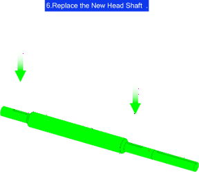
• Split the Chain: Locate and remove the connecting master link to split the roller chain loop.
COMMISSIONING & QUALITY CONTROL TESTS
Manual Rotation Check
- Before restoring power, place a pipe wrench onto the exposed portion of the shaft or turn the drive mechanism manually.
- Rotate the assembly through two complete revolutions of the conveyor chain.
- Verify that no binding, tooth interference, catching, or severe friction occurs.
Powered Jog Test
- Clear all tools from the conveyor area and ensure all personnel are at a safe distance.
- Remove all LOTO padlocks and tags from the primary isolator. Restore electrical power.
- "Jog" the motor (turn the switch on for less than one second and turn off immediately) to visually confirm the correct directional rotation and smooth initial chain take-up tracking.
Operational Test Run
- Operate the conveyor under zero-load conditions (empty) for a continuous duration of 15 to 30 minutes.
- Throughout the test run, perform the following validation protocol:
- Acoustic Inspection: Listen closely for any clicking, grinding, or popping noises indicating misalignment or poor chain-to-tooth meshing.
- Vibration Audit: Check for unusual structural vibrations along the frame and bearing mounts.
- Thermal Verification: Use an infrared thermometer to verify pillow block bearing temperatures remain within normal operating ranges and do not overheat.










Copyright © 2026 Fluent Conveyors, LLC. All rights reserved.

The Fluent Conveyors logo is a registered trademark of Fluent Conveyors, LLC. Serial Number 97664258 Registered on Dec. 12, 2023


