









Copyright © 2026 Fluent Conveyors, LLC. All rights reserved.

The Fluent Conveyors logo is a registered trademark of Fluent Conveyors, LLC. Serial Number 97664258 Registered on Dec. 12, 2023


Copyright © 2026 Fluent Conveyors, LLC. All rights reserved.
The Fluent Conveyors logo is a registered trademark of Fluent Conveyors, LLC. Serial Number 97664258 Registered on Dec. 12, 2023
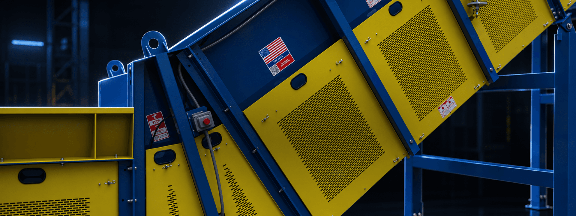
US workplaces recorded 213 deaths in 2024 from workers being struck, caught, or compressed by running powered equipment, according to the Bureau of Labor Statistics. Conveyors create certain unavoidable hazards, but many can be reduced or removed through smart conveyor design and improved personnel training.
Reduce conveyor hazards at your operation by guarding nip points and drive components, isolating stored energy before maintenance or jam clearing, keeping emergency stops within reach, inspecting safety devices on a set schedule, and designing equipment so fewer tasks require workers to reach into hazardous areas.

Most powered conveyors concentrate risk where moving parts meet fixed components, where material changes direction, and where energy remains stored after shutdown. The components that make up a conveyor create hazards in consistent locations.
Drive type determines which hazards are present. Roller chain conveyors carry the belt on chain running along rail, so exposure is concentrated around sprocket engagement, the chain return, and the take-up assembly.
On pulley-driven machines, the same drive function creates a different set of hazards. Nip points form where the belt wraps around the head and tail pulleys, while the return run adds belt-to-idler contact at roughly knee height along the frame.
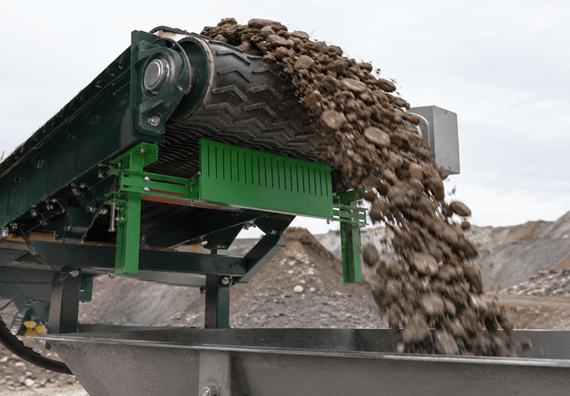
Material handling adds another set of risks. Loading zones, chutes, and discharge points can expose workers to impact and falling material. Elevated runs can put those hazards above people working below.
Containment hardware creates additional pinch points. Conveyor skirting creates a pinch line against the belt that maintenance staff may reach into during adjustment. Belt cleaners create similar exposure at the discharge end.
Ask yourself: “Does the operator need to be within reach of the hazard at all?” NIOSH ranks controls from elimination and substitution through engineering controls, administrative controls, and PPE. Higher-level controls are more reliable because they don’t depend on workers making the right decision under production pressure.
Applying a contact and hazard reduction hierarchy to a conveyor looks like this:
A formal conveyor risk assessment provides structure for the first three steps and creates a written record for later audits.
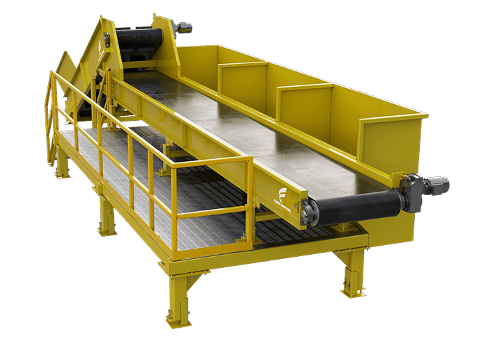
Access geometry is decided during engineering. Those decisions determine how often workers will need to enter a hazard zone over the life of the conveyor. If a grease fitting can only be reached by leaning past a sprocket guard, that guard is more likely to be removed and left off.
Practical design choices that reduce exposure include:
Retrofits follow the same principle on a smaller scale. Relocating a grease line, adding an inspection port, or moving a disconnect can permanently remove recurring exposure. That is why safety and compliance planning should be part of the equipment scope.
Guarding decisions depend on:
What workers can reach
How often the area needs to be opened
What happens when it is opened
Fixed guards protect from components that are not accessed between shutdowns, including drive sprockets, shafts, and couplings. Interlocked guards are suited to access points opened during normal production because the interlock stops motion before access is available. Guarding by distance or location works when the hazard is far enough above or behind a barrier that workers cannot physically reach it.
Reach gaps are a common inspection problem. A guard may block access from the front while still allowing a hand to reach over the top, beneath the frame, or through an expanded metal opening. The OSHA guarding requirements for conveyors cover opening sizes, distances, and construction in more detail.
Two often overlooked areas include the return run (where the belt and idlers may sit at ankle height under the frame) and the take-up assembly (where pinch points and stored tension exist within the same small area).
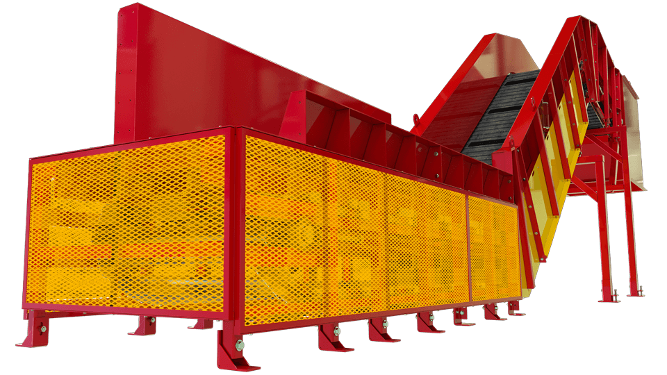
Exposure changes with the task, so hazard controls should address the work being performed. Once a task requires reaching past a guard line or into the load path, energy isolation is necessary.
For example, belt tracking adjustments are often made while equipment is running because belt movement must be observed under load. That can put hands near a moving belt edge. Moving adjustment points outside the reach envelope removes the exposure rather than relying on a procedure to manage the hazards.
Conveyor lockout/tagout is sometimes reduced to switching off the disconnect, but that only addresses one energy source. NIOSH defines hazardous energy control as preventing unexpected energization, startup, and release of stored energy. Conveyors can retain several forms of energy after electrical power is removed.
Energy sources on a stopped conveyor include:
Electrical: drive power, control circuits, and separately fed accessories such as heaters or oilers
Gravity: material on an inclined conveyor that can run back when the drive is released
Mechanical tension: force stored in the take-up system and across the belt or chain
Rotational: coast-down in the drive, gearbox, and loaded pulleys after the stop command
Hydraulic or pneumatic: tensioners, diverters, gates, and clamping devices
Material: loads that can shift, settle, or release when a blockage is disturbed
Verification is the final step. Isolate the source, release or restrain stored energy, and test the start control to confirm that nothing moves before work begins. Releasing belt tension before splicing belongs within that sequence and should happen before hands-on work starts.
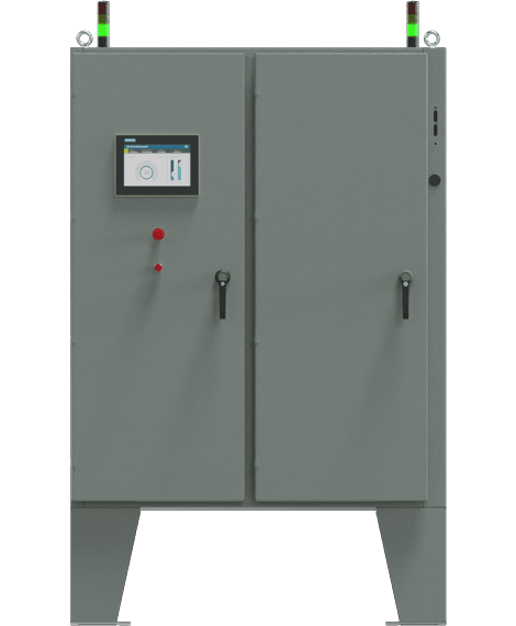
Walk the conveyor from every routine work position and confirm that an e-stop is reachable, including positions used during cleanup and jam clearing.
For long runs, use pull cord systems. A cord running along the carrying side of a long conveyor gives workers a stop they can reach without searching for a button. Pull cord systems only remain effective when cord tension and switch travel are maintained. The environment also affects device selection because wash-down and dust-heavy areas often require special enclosure ratings.
An e-stop halts motion but does not isolate energy. Power remains connected, stored tension remains loaded, and the device can be reset from the panel. Lockout still applies before anyone reaches into the conveyor. Our guide to conveyor e-stop systems covers device types, placement spacing, and circuit behavior in more detail.
Beyond the stop circuit, conveyor control systems can perform additional safety functions. Interlocks, zero-speed and belt-drift switches, start warning horns, halo lights at pinch-heavy transfers, and wireless stop devices on long or remote runs can reduce exposure without depending on workers to react first.
These circuits need a reliability level appropriate to the risk they control. ISO 13849-1, a primary safety standard, addresses architecture, redundancy, and diagnostic coverage requirements in detail.
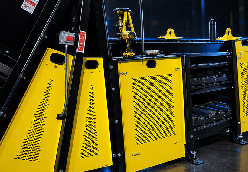
Safety devices can fail without affecting normal production. A pull cord can go slack, a guard can be reinstalled with only two of six fasteners, or an interlock can be bypassed during a repair and never restored. The conveyor may continue running normally, which makes regular safety inspection critical.
Set inspection frequency based on operating conditions and the maintenance calendar. Our component replacement intervals page provides a baseline for inspection frequency.
Training should focus on the tasks that create exposure. Operators need the loading, clearing, and restart procedures for their specific machine. Maintenance staff need to know the isolation points, stored energy sources, and blocking requirements for each planned job. Contractors and temporary workers need the same information before their first shift because they have less machine-specific knowledge.
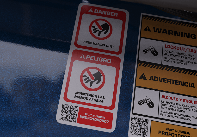
Labels reinforce that training between refreshers. Hazard labels follow the ANSI Z535.4 format for signal words, color, and layout, making severity easier to recognize at a glance.
The CEMA safety label set covers conveyor-specific hazards that general safety catalogs may not, including nip points, chain drives, and elevated discharge. Labels can be painted over or worn away in abrasive service, so replacement should be part of the inspection program rather than left until repainting.
Machine documentation fills in the remaining details. Isolation points, guard locations, and service access should be identified in the owner's manual that stays with the equipment.
OSHA regulations and consensus standards cover overlapping areas but carry different authority. The construction conveyor rule at 29 CFR 1926.555 incorporates ANSI B20.1-1957 by reference, while the current consensus standard is ASME B20.1-2024. General industry conveyor work is governed by machine guarding, power transmission, and energy control rules rather than one conveyor-specific section. Our OSHA compliance page explains which sections apply to different types of conveyor work.
OSHA enforces requirements on employers at the worksite. Manufacturers build equipment to align with applicable standards and provide guarding, labeling, and documentation that support compliance. Fluent machines align with ANSI/ASME B20.1 for guarding, stop provisions, labeling, and access.

Use this list during walkarounds of existing equipment and when specifying new conveyors:

Guarding, isolation, and access are less expensive and more effective when addressed during engineering. Fluent builds custom conveyors for recycling, waste, aggregate, and heavy industrial operations.
We address guard geometry, isolation placement, and maintenance access to minimize hazards during design. If you are specifying a new line or correcting a machine that repeatedly puts workers inside hazardous areas, our engineers can help identify and address the underlying problems so your next conveyor works better and safer.
